RISC-V CPU & custom GPU on an FPGA Part 2 – RISC-V ISA
In this part of the series we’ll take a very quick look at the RISC-V ISA, especially the bits that interest us. Most of the ISA can be safely skipped as it’s organized into a series of ‘feature levels’, out of which only one is mandatory to implement (namely the base integer set, I)
If we check the ISA manual, at the time this series was written, we’d see that RV32I ISA module was marked as ‘frozen’ which is the one we’re going to implement. It’ll save us time and FPGA surface area to keep things simple and 32 bit is more than enough for majority of operations for the system we’re implementing.
For RV32I, since we’re also skipping the compressed instruction set for now to keep things clean, there is one instruction size: 32bits. Every single instruction is encoded as such, which makes life so much easier when loading instructions from memory, when calculating addresses or decoding them.
In the RV32I world, we have 32 registers in total, plus the program counter, and 32 more for floating point arithmetic. On top of this, there are some special registers out of which we’ll implement only a few, namely the CSRs (control status registers) . These registers store machine state, control interrupts and store/set other meaningful machine states. And lastly, the CPU we’re implementing will run in ‘machine mode’ which is the highest privilege level. Since we’re not running a real OS on this thing yet, we can focus on bringing everything up in machine mode and then move on to other levels of execution.
Instruction formats
RISC-V instructions are really simple and there are only a few classes of them, with quite a bit of variants for some. To start with, they’re grouped into distinct types:


For uncompressed RV32I instructions, the lowest two bits are always set to 11 in binary. This makes implementation of the decoder a little bit smaller since we don’t need to care about these bits, unless we wish to trap illegal instructions in a different encoding (such as when running a compressed instruction program on our non-compressed architecture)
Registers
There are four basic type of registers on RISC-V. These are the integer registers, PC (program counter) register, floating point registers, an the CSRs.
For the integer register file, registers are internally named from x0 to x31. The register x0 is special, because it is not writable, and will always return the value 0. This is handy for a lot of cases where a hard-coded zero can let us implement non-existing instructions. For example, we can encode a ‘nop’ instruction, which doesn’t actually exist in the RISC-V ISA, as a ‘addi x0, x0, 0’ instruction. This will essentially do nothing since we can’t write back the value x0+0 (which is a zero) to the non-writable x0 register.
When it comes to floating point registers, however, there are no zero registers, but we do get a floating point control and status register; ‘fcsr’. In our implementation this register will not be a part of the design initially to get things rolling, but will probably become important once we wish to work with rounding modes and exceptions.
The third type, CSR registers are special control and status registers, and cover an index range of 0 to 4095. There are some reserved ones, and some user CSRs that an implementation can use. We’re mostly going to be interested in the machine interrupt status ones, and the time/cycle/retired instruction counters for performance and timer interrupt reasons.
32 bit CSRs
- fcsr: Floating point status and control register (rounding modes, exceptions etc)
- mip: Machine interrupt pending (used to flag pending interrupts)
- mcause: Machine interrupt cause (cause marks which machine state is causing the interrupt)
- mie: Machine interrupt enable (when set, each bit controls a specific machine interrupt to fire)
- mtvec: Machine interrupt vector (the address to branch to when servicing interrupts)
- mstatus: Machine interrupt status (global interrupt enable and other control bits)
- mepc: Machine interrupt program counter (return PC to use when returning from interrupt handler)
64 bit CSRs
- time: Wall clock time ticking independent from instruction cycle counter
- timecmp: Comparison register to trigger a timer interrupt when time crosses this value
- cycle: Instruction cycle counter
- reti: retired instruction count
In the ISA documents, timecmp CSR is shown to be a memory mapped register. For ease of implementation, and to avoid any timing failures due to memory read latencies, we’ll put it into a user CSR and map it onto two 32 bit registers (0x800 and 0x801). There are quite a few CSR indices, from 0 to 4095, so we have plenty left over for other things, if we ever need to add more special control bits.
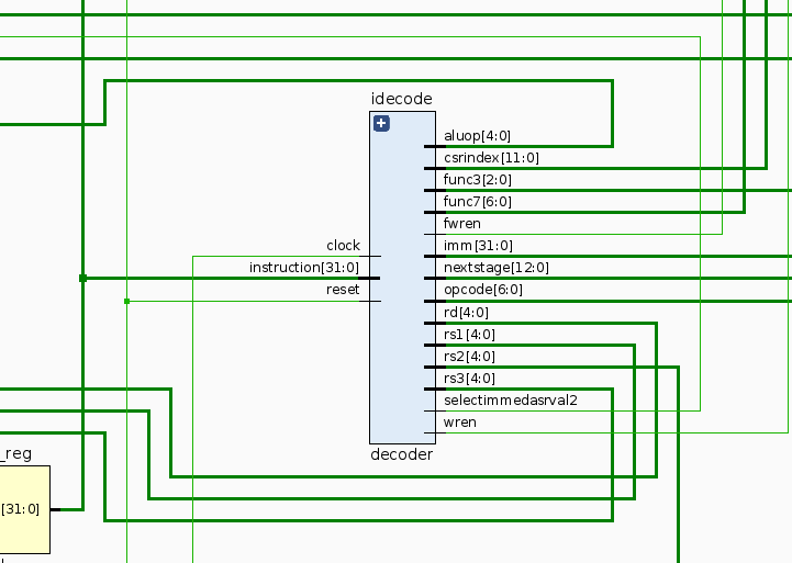
Instruction Decoding
We now have sufficient reason to have a look at the instruction decoding.
The lowest 7 bits of each 32bit word instruction we read from memory stores the actual opcode. Some opcodes split into variants, so these opcodes sometimes act as junctions to reach a subset of instructions. For instance, the integer ALU operations are essentially the same opcode, and split into 8 different types using 3 bits of markers, and one of them splits further into two using one bit (ADD/SUB). This nature of things also greatly simplifies the decoder as we will see later on.
Let’s decode one instruction to see how we’d go about doing it: 24f05a63 : blez a5, 0x7f4
This yields the following binary pattern (with least significant bit on the right)
0010010 01111 00000 101 10100 1100011Looking at the rightmost two bits, we know this is a 32bit non-compressed instruction. Checking the following 5 bits (11000) we can see that this is a member of the BEQ/BNE/BLT/BGE/BLTU/BGEU instuction set. Checking the three bits 14 through 12 (101), we can see that it’s a BGE instruction. And right at the leftmost side we can see an immediate encoded into top 7 bits and bits 11 though 7, which when decoded and sign extended read as a 32 bit integer 0x7F4.
Following the decoding table further at page 104 of the RISC-V ISA, we get the full instruction to read as ‘BGE zero, a5, 0x7f4’. Well, but this doesn’t look anything like a ‘BLEZ’. That’s because there’s no BLEZ instruction, and it’s only our interpretation that creates this alias. If we look at the operation here, it’s actuall ‘if zero > a5’, which can be reinterpreted as ‘if a5 <= zero’, and that gives us our BLEZ instruction.
Often, we’ll see this kind of instruction aliasing in many places in disassembled code, and in those cases it’s useful to refer to the pseudo-instruction list at the end of the same ISA document to save some time.
If you’ve noticed the pattern from the ISA documentation: we have groupings that are fixed in place for most of the source/destination registers, the instruction itself, and somewhat the immediate values. This will also become interesting when we’re implementing the hardware.
This concludes part 2. On the third part, we’ll get started with hardware components required to implement out first bits on the actual board.